Moving, rotating and adjusting cross sections with the 3D cursor
Depending on the type of cross section (planar, vertical or surface-parallel), you can move, rotate and/or graphically adjust it with the help of the 3D cursor.
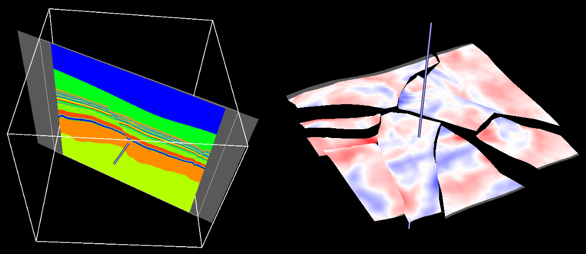
Moving cross sections with the 3D cursor click to enlarge
Moving a cross section with the help of 3D cursor
This functionality can be applied to planar and surface-parallel sections, not to vertical sections.
You can move the section using the 3D cursor. To do this:
- Press the Shift key on your keyboard and click on the desired planar or surface section.
- While holding down the Shift key, move your mouse along the stick that is displayed.
The movement is always in the direction of the plane normal. For surface-parallel sections, the movement direction depends on the type assigned to the source tri-mesh. Horizon slices move along the z-axis while fault slices move perpendicular to the azimuth of the fault.
The intersections displayed on cross sections are instantaneously updated while the canvas is being moved. If performance is negatively effected when moving the canvas you can turn off the Show details while moving option ( ) in the 3D view toolbar. This will increase performance when moving the canvas but hide the model detail during movement; model detail is restored when the movement finishes. Planar cross sections move in the direction of the plane normal.
Rotating a planar cross section with the 3D cursor
This functionality can be applied to planar sections, not to vertical or surface-parallel sections.
You can rotate planar sections with the help of the 3D cursor. To do this:
- Press the Spacebar on your keyboard and click on the desired location on the planar section. A red stick perpendicular to the plane appears.
- While holding down the Spacebar, click on the yellow end of the stick and move it along the displayed sphere to the desired orientation. The circles displayed with the sphere help to orient the planar section with respect to coordinate reference system axes.
By default, intersections are updated while the cross section is being modified. You can prevent these immediate updates, due to preference or performance issues, by turning off the Show details while moving () option in the 3D View toolbar.
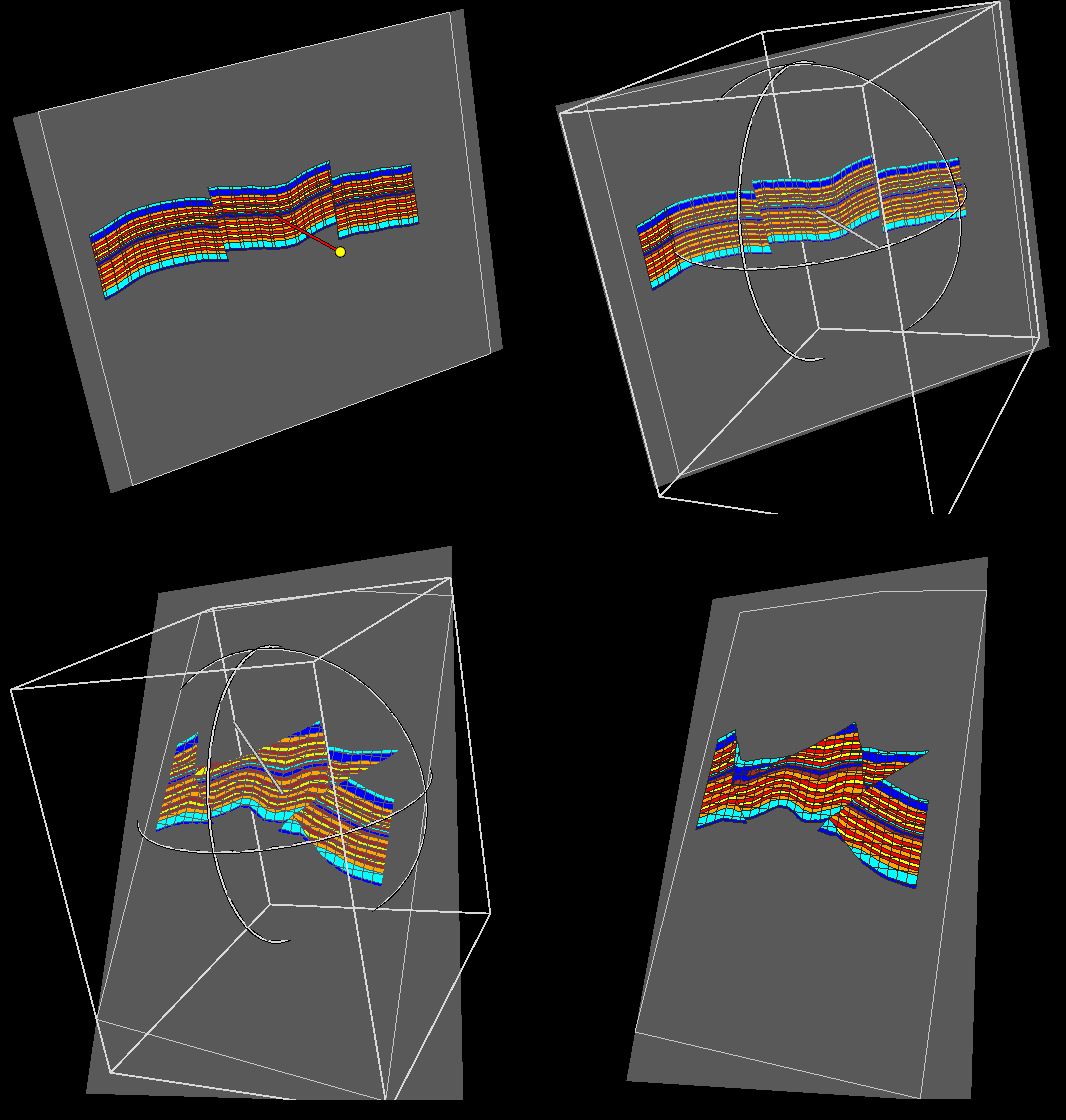
Rotating a cross section with the 3D cursor click to enlarge
Graphically adjusting a vertical cross section
Note that this functionality can be applied to vertical sections, not to planar or surface-parallel sections.
Using the 3D cursor, you can graphically adjust the position of vertical sections. To do this:
- Press the Shift key on your keyboard. The nodes at the end of the pane lines will be visible as small white spheres.
- Keeping the Shift key pressed, click on the node you want to move and drag it to the desired location.
Only vertical sections not associated with objects can be edited in this way. Nodes based on wellbore trajectories cannot be moved but will automatically update when the well location is updated, e.g., when well plans are modified. This means that you can move well targets and see the corresponding cross section being updated instantaneously.
By default, intersections are updated while the cross section is being modified. You can prevent these immediate updates, due to preference or performance issues, by turning off the Show details while moving () option in the 3D View toolbar.
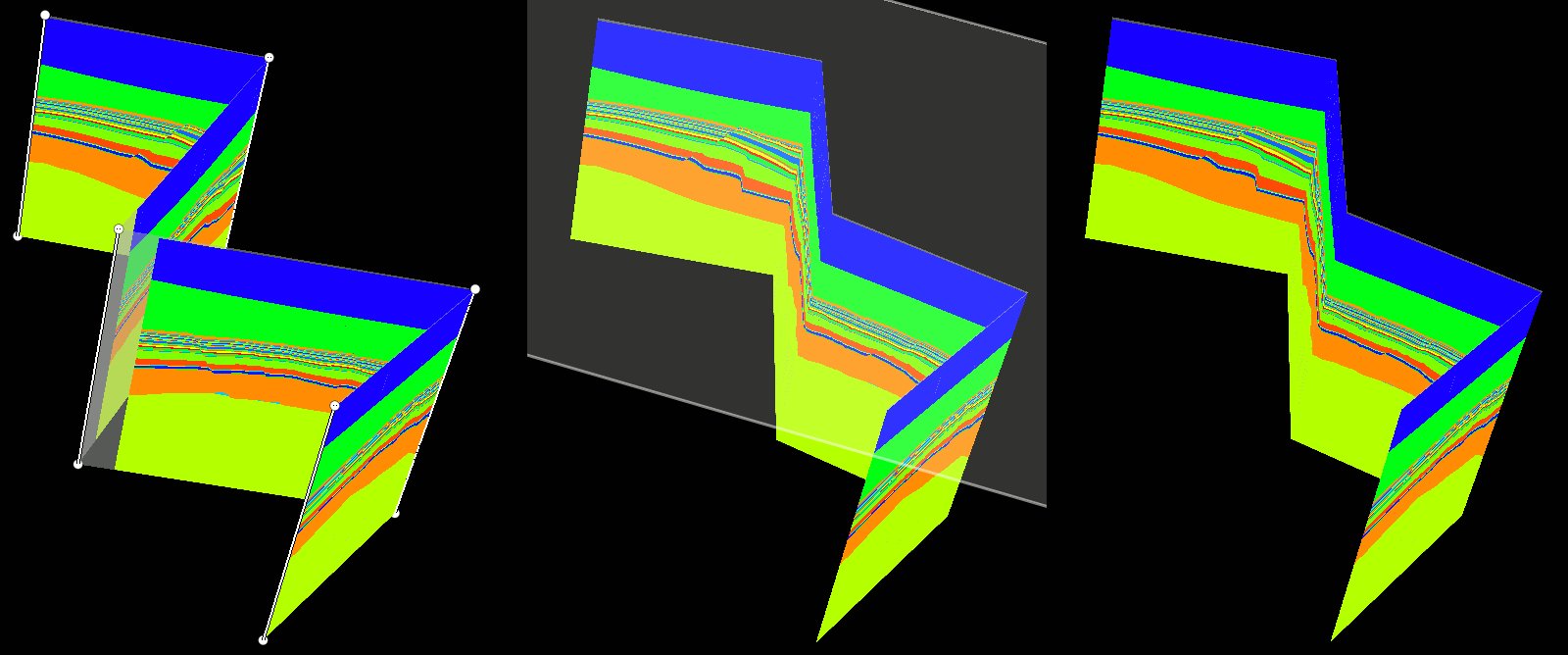
Moving a node of a vertical section click to enlarge